Frame, Cylinder and Running Gear
Work is being performed by Steam Operations Corporation at their shop located at Listerhill TMC in Muscle Shoals, AL.
The project is being managed by Mr. Scott Lindsay of Steam
Operations Corporation.
![]()
|
Old cylinders were sand blasted on site. Left and right castings were reassembled for laying out the dimensions for "as built" machining parameters. 786 Frame in the background View of part of the TMC shop complex
|
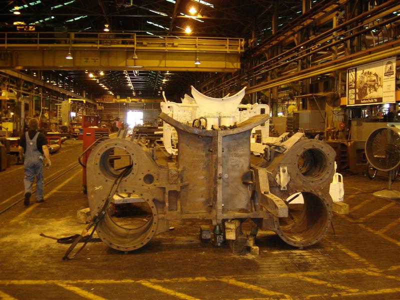 Photo: Steam Operations Corporation |
| Old cylinders bolted together and being moved around the shop complex |
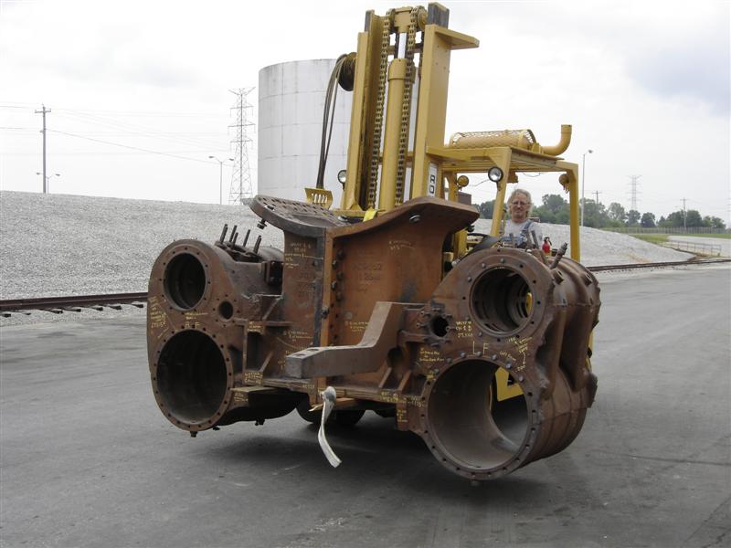 Photo: Steam Operations Corporation |
|
Layout of old cylinders.
|
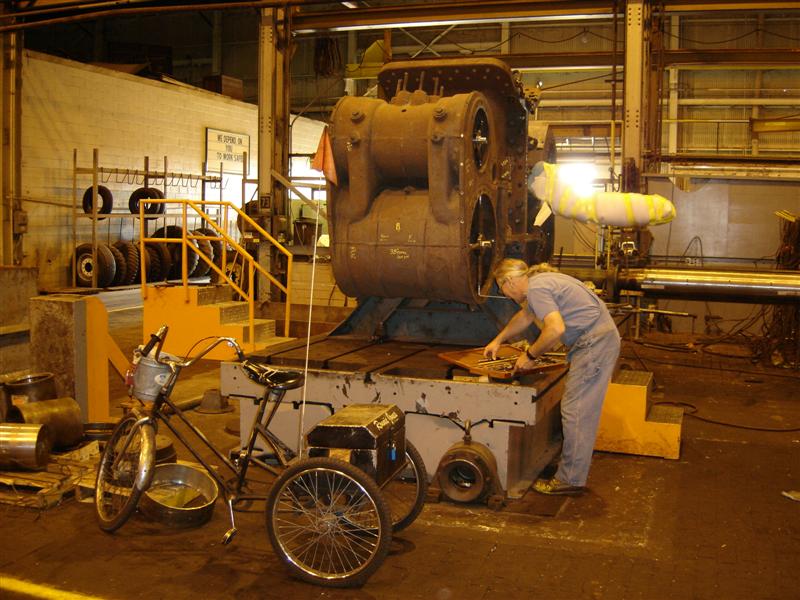 Photo: Steam Operations Corporation |
|
Laying out machining dimensions as found on old cylinders.
|
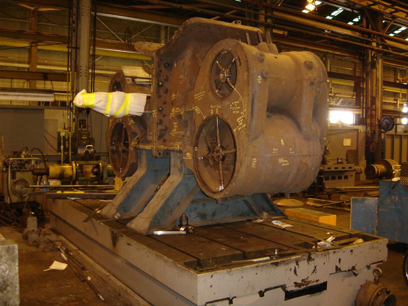 Photo: Steam Operations Corporation |
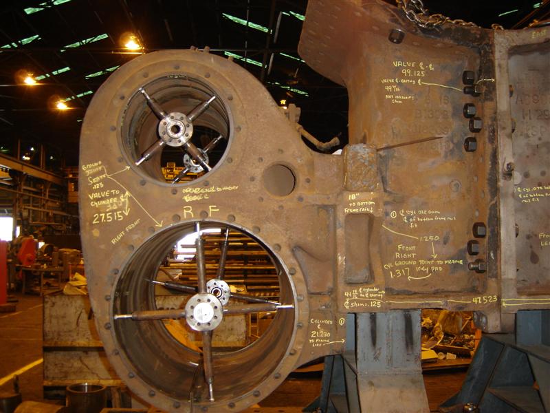 Photo: Steam Operations Corporation |
|
|
Old cylinders set up for measuring showing size of the shop complex.
|
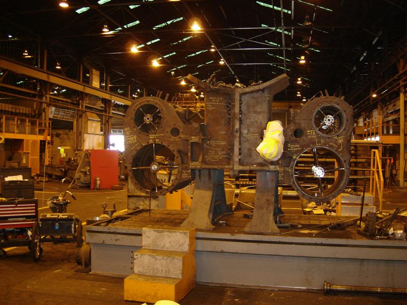 Photo: Steam Operations Corporation |
|
New cylinders prior to machining.
|
 Photo: Steam Operations Corporation |
|
New cylinder initial layout.
|
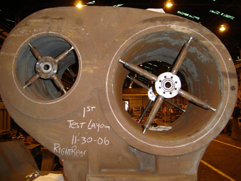 Photo: Steam Operations Corporation |
|
Punch marks are made on the new cylinders during layout serve as double check to CAD layout. (In the "old days", the punch mark system was used by the builders of steam locomotives; the old marks are occasionally seen on the original 786 cylinders and frame.) |
 Photo: Steam Operations Corporation |
|
Layout of cylinder center line.
|
 Photo: Steam Operations Corporation |
|
Rough cut of lower frame fit on cylinder half.
|
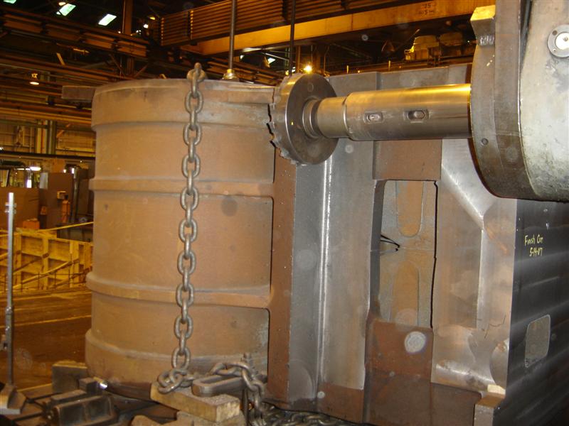 Photo: Steam Operations Corporation |
|
Ronnie Jones reviewing CAD layout of cylinder mating holes prior to drilling. these holes are used to bolt the left and right castings together.
|
|
|
CAD design of bolt holes that secure the cylinder castings together. The layout ensured minimal misalignment of the holes when set together for reaming and fitting the taper bolts.
|
 Photo: Steam Operations Corporation |
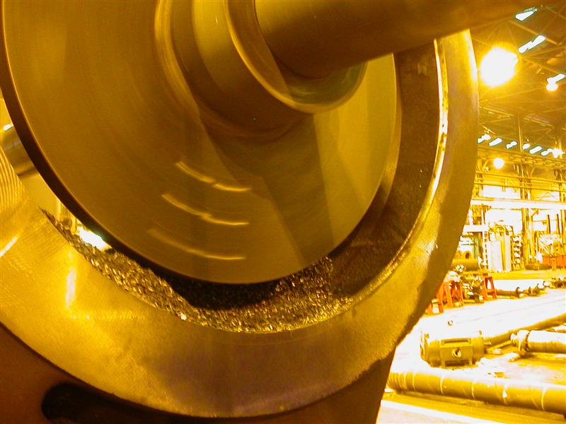
| One half of the cylinder saddle on a smaller horizontal boring mill undergoing an initial roughing cut. One pass though the bore takes 2 hours. |
 |
| The boring head near the end of the roughing pass. The finished bore is approximately 26" diameter, however, the last inch of diameter will be removed in one of the final machining operations before the cylinders are finally mounted on the frame. |
 |
|
Drilling holes at casting part line.
|
|
|
CAD layout of branch pipe flange.
|
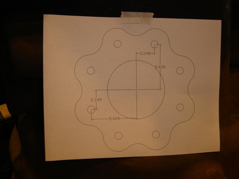 Photo: Steam Operations Corporation |
|
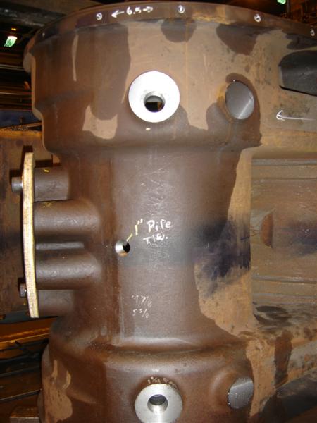
Branch pipe stud hole layout.
|
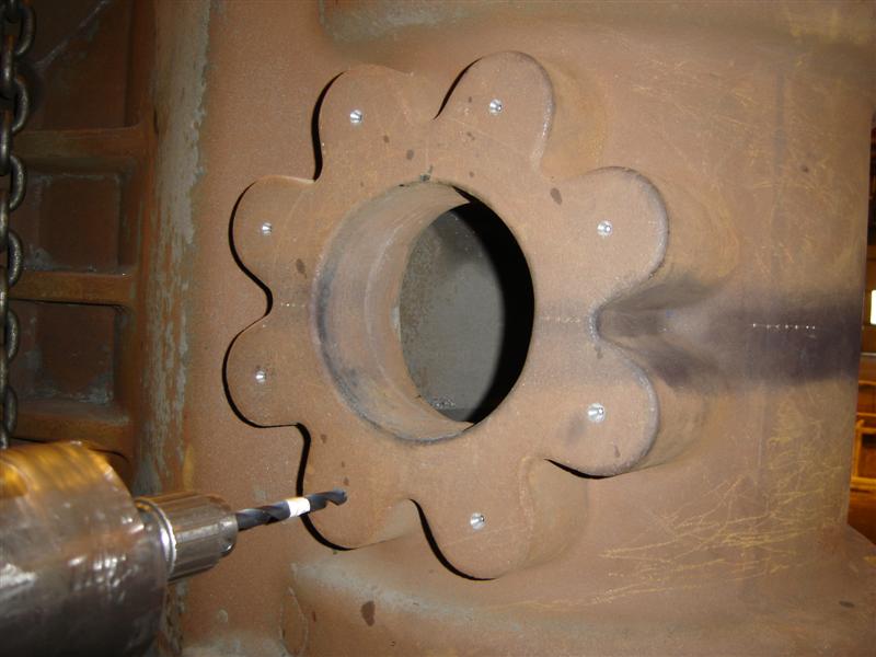 Photo: Steam Operations Corporation |
|
Branch pipe stud holes drilled and tapped.
|
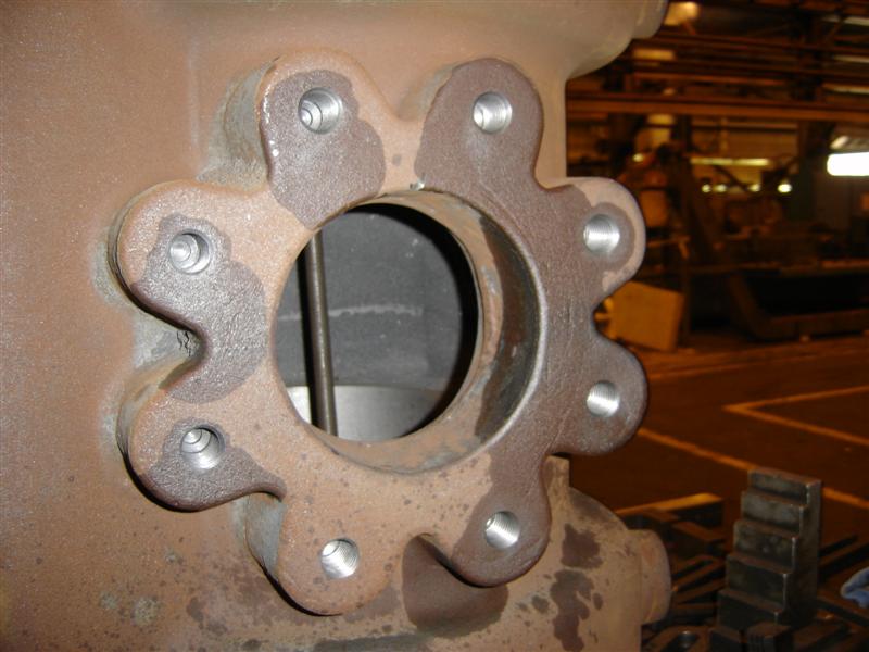 Photo: Steam Operations Corporation |
|
Completed branch pipe flange and seat.
|
 Photo: Steam Operations Corporation |
|
jacket stud holes
|
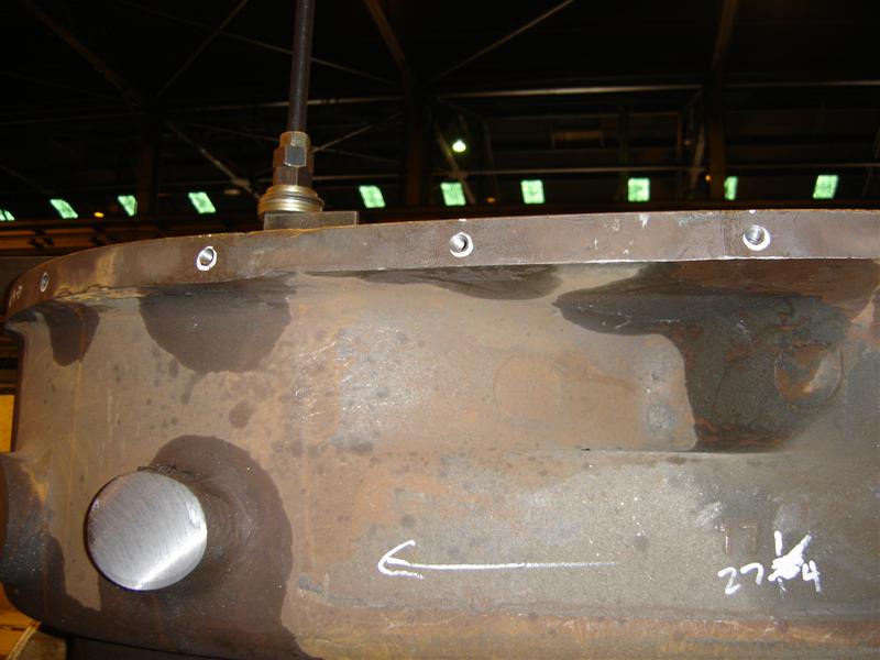 Photo: Steam Operations Corporation |
|
Port plug holes and cylinder house valve hole complete.
|
|
|
Taper bolts being machined.
|
|
|
New cylinders mated together and taper bolts being applied.
|
 Photo: Steam Operations Corporation |
| Back view of the new cylinder halves assembled with taper bolts. |
 Photo: John Mandell |
| Another view of the new cylinder halves secured with taper bolts. |
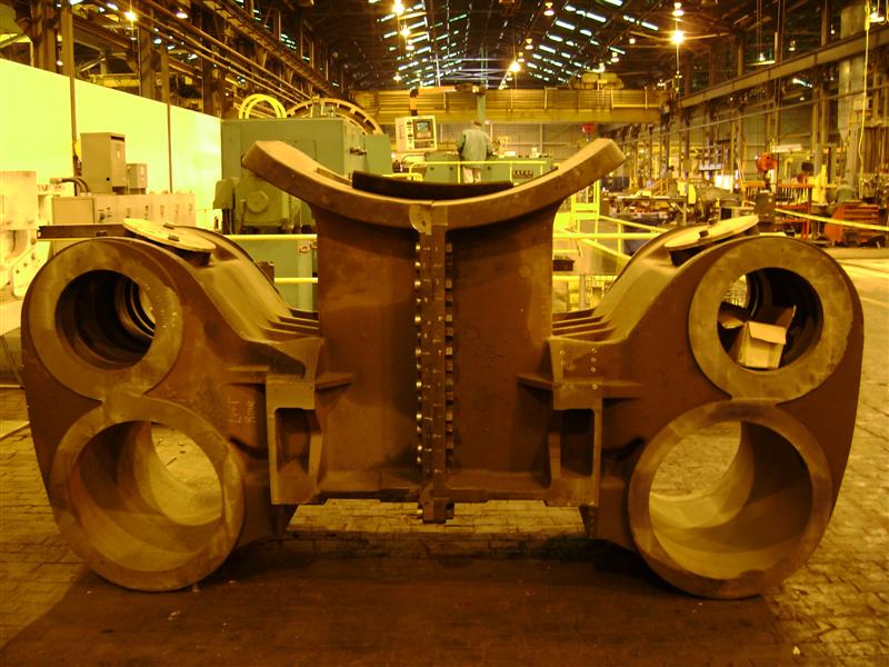 Photo: Steam Operations Corporation |
| Another view of the new cylinder halves secured with taper bolts. |
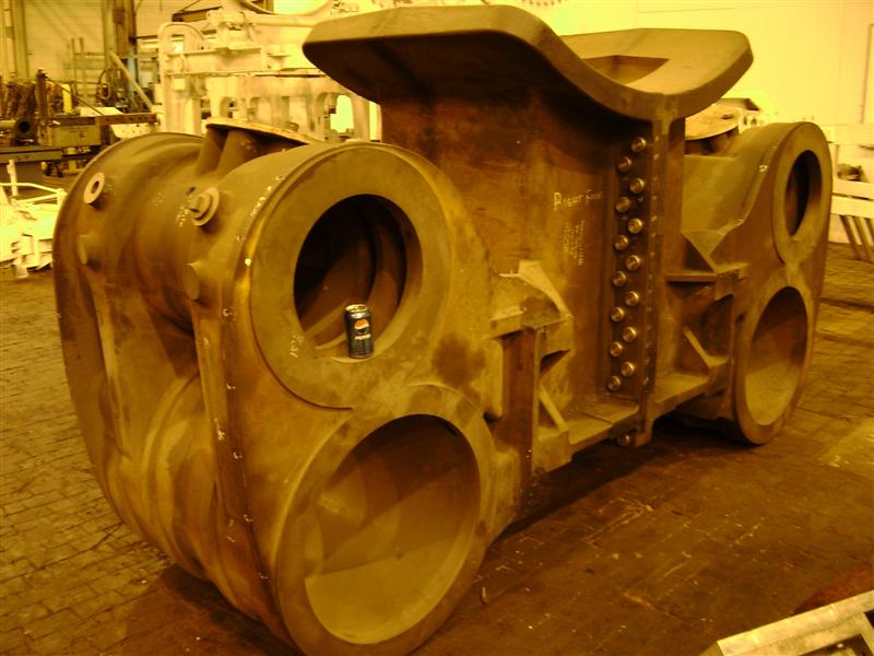 Photo: Steam Operations Corporation |
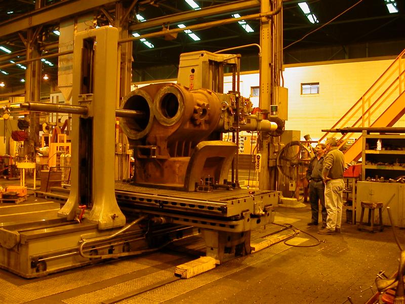
| The big Horizontal Boring mill being installed at TMC (referred to as a "bar"). 786's cylinder saddle will be one of the first items machined on this new Boring Mill. With this new mill, 786's cylinder saddle pair can be machined in one setup, assuring perfectly parallel bores. |
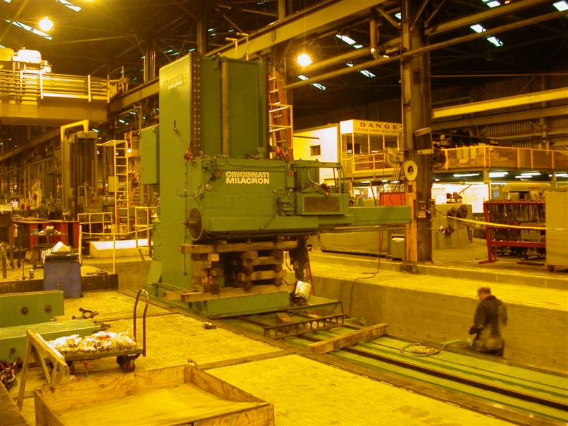 Photo: John Mandell |
| Another view of the bar, getting ready for operation. |
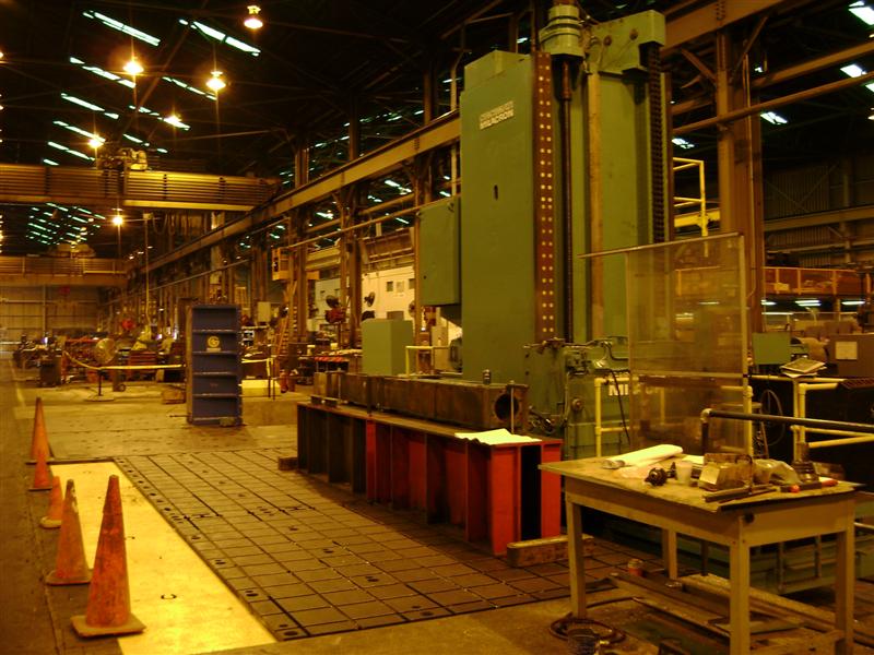 Photo: Steam Operations Corporation |
| 786 Frame staged at TMC, waiting for new cylinders and running gear. |
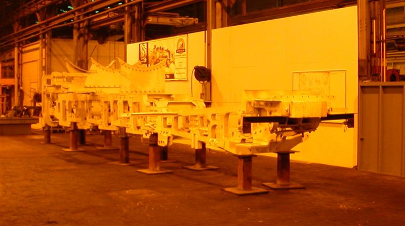 Photo: John Mandell |
| 786 Frame with new cylinders |
 |
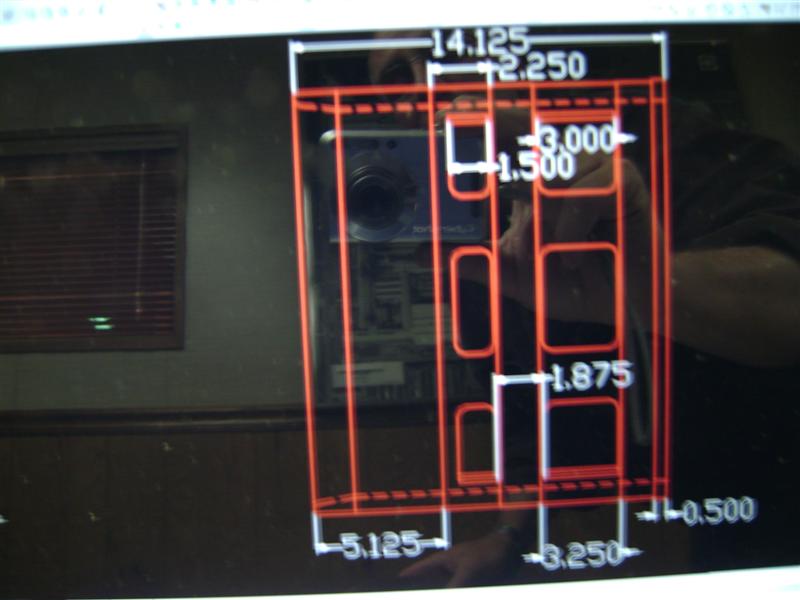
| Initial design & layout of the Valve Cage |
 |
![]()